Device introduction
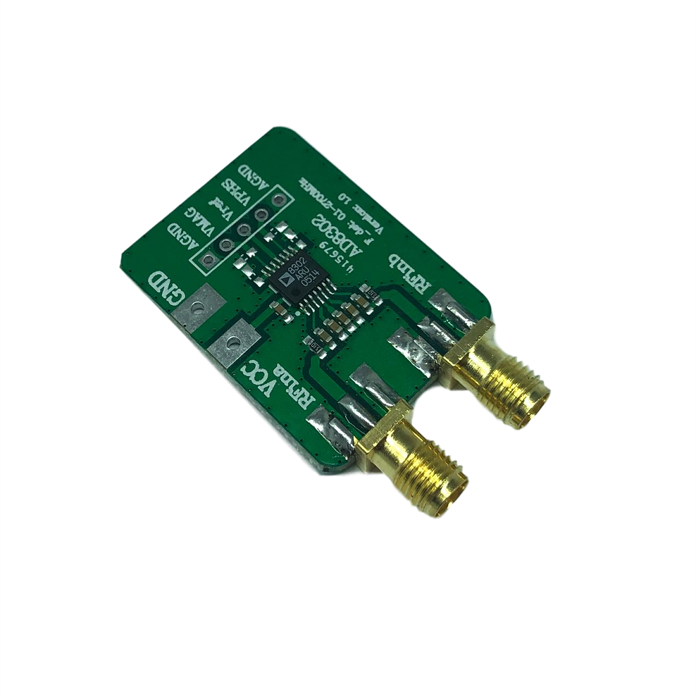
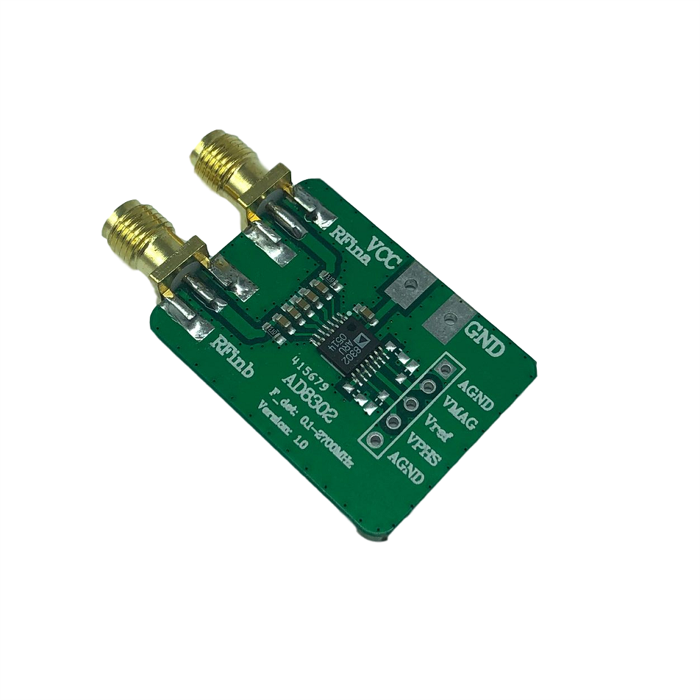
1. The relative amplitude and phase detector of radio frequency signal, using AD8302 chip, is a fully integrated RFIC, used to measure the amplitude and phase between two independent input signals. The operating frequency of this device can be from low frequency to 2.7GHz. Can be used for gain detection, standing wave ratio measurement.
2. AD8302 built-in two precision matched broadband logarithmic amplifiers, a broadband linear multiplier/phase detector, 1.8V precision reference voltage source, and analog output proportional operation circuit. The input signal range is -60dBm to 0dBm (reference impedance 5092), and the corresponding dynamic range is 60dB.
The AD8302 output provides accurate amplitude in the range of +/-30dB, with a slope of 30mV/phase value ranging from 0 to 180, and a slope of 10mV degrees.
3. AD8302 is a monolithic integrated circuit used for RFIF amplitude and phase measurement. It is mainly composed of two precision-matched broadband logarithmic detectors, a phase detector, an output amplifier group, a bias unit, and an output reference voltage buffer. The composition can simultaneously measure the amplitude ratio and phase difference between two input signals in the frequency range from low frequency to 2.7GHz, which can be applied to the measurement of the linear ratio of RFIF power amplifiers, the precise control of RF power, the measurement of standing wave ratio and the measurement of remote systems. Monitoring and diagnosis, etc.
4. AD8302 mainly has three working modes:measurement, controller and level comparator, but its main function is to measure amplitude and phase. AD8302 makes the amplitude measurement range up to 60dB through two width logarithmic detectors, and the detection range of the independent phase detector can reach 180. The amplitude and phase measurement equation is VMAG=VSLPLOG(VINA/VINB)+VCP; VHS=VO[O(VINA)-O(VINE)]+VCP
When the chip output pins VMAG and VPS are directly connected to the chip feedback setting input pins MSET and PSET, the measurement mode of the chip will work at the default slope and center point (the scale factor for accurate amplitude measurement is 30mVdB, and the scale factor for accurate phase measurement is 30mVdB. It is 10mV degree, the center point is 900mV).
Specification
1. It can measure the gain (also known as amplitude ratio) and phase difference of two input signals in the frequency range of low frequency to 2.7GHz; AD8302 can not only measure the gain and phase difference of amplifiers, mixers and other circuits, but also is particularly suitable for wireless Base station and test equipment for testing;
2. When measuring the gain, the dynamic range of the two input signals is ÷30dB, and the sensitivity of the output level is
30mVdB, the error is less than 0.5dB. The output voltage corresponding to -30dB is 30mV, and the output voltage corresponding to +30dB is 1.8V. The output current is 8mA, the conversion rate is 25VuS
3. The scale factor of accurate amplitude measurement is 30mVdB;
4. The precise typical value is less than 0.5dB; (AD8302 measures the phase difference in the range of 0~180, the corresponding output voltage range is 0~1.8V, the output voltage sensitivity is 10mV/(), and the measurement error is less than
0.5. When the phase difference p=0”, the output voltage is 1.8V; when p=180, the output voltage
It is 30mV and the output current is 8mA. The conversion rate during phase output is 30MHz, and the response time is 40ns 500ns (depending on the measured phase difference);)
5. The scale factor of accurate phase measurement is 10mV()
6. The accurate typical value is less than 1;
7. When the device is in operation, it has three working modes:measurement, control and level comparison;
8. With a stable 1.8V reference voltage bias output;
9. The video bandwidth response is 30MHz;
10. Working with a 2.7V~5.5V single power supply;
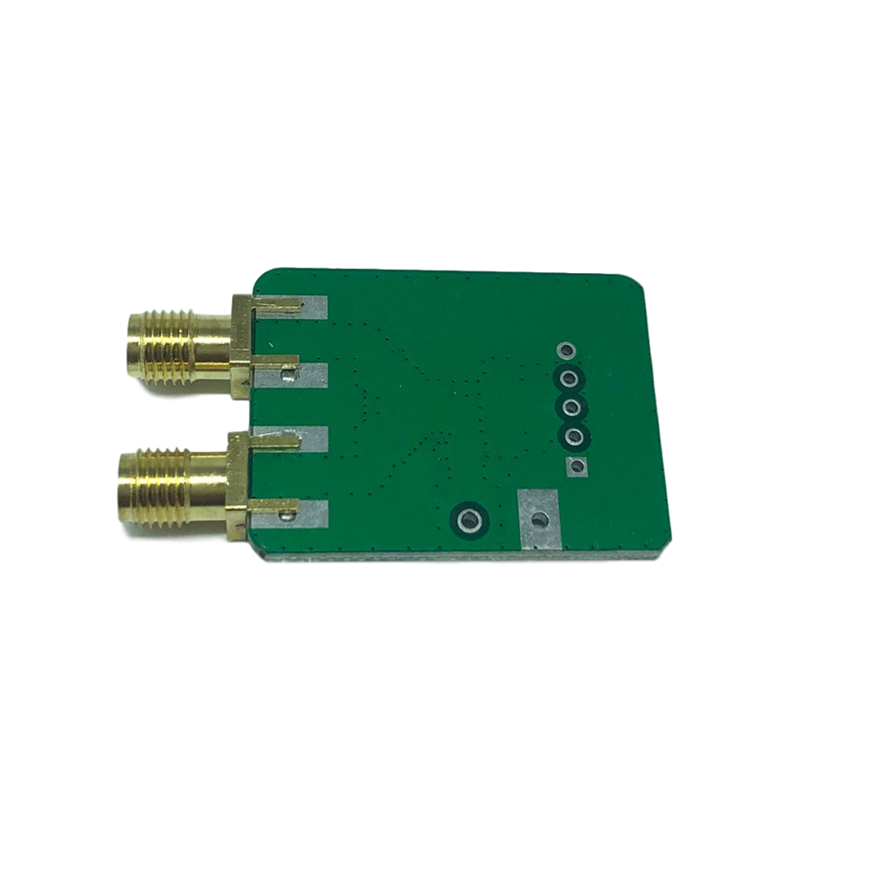
11. Product size:30*25MM
12 Product weight:6g
Package included
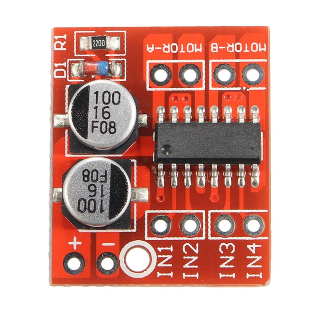
1 x AD8302 RF Amplitude and Phase Detector
Additional information
| Weight | 0.01 kg |
|---|






Reviews