

Feature
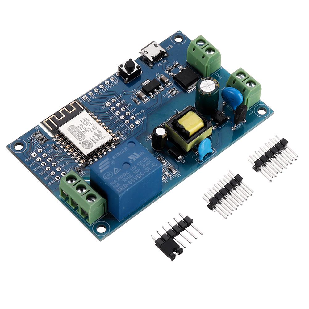
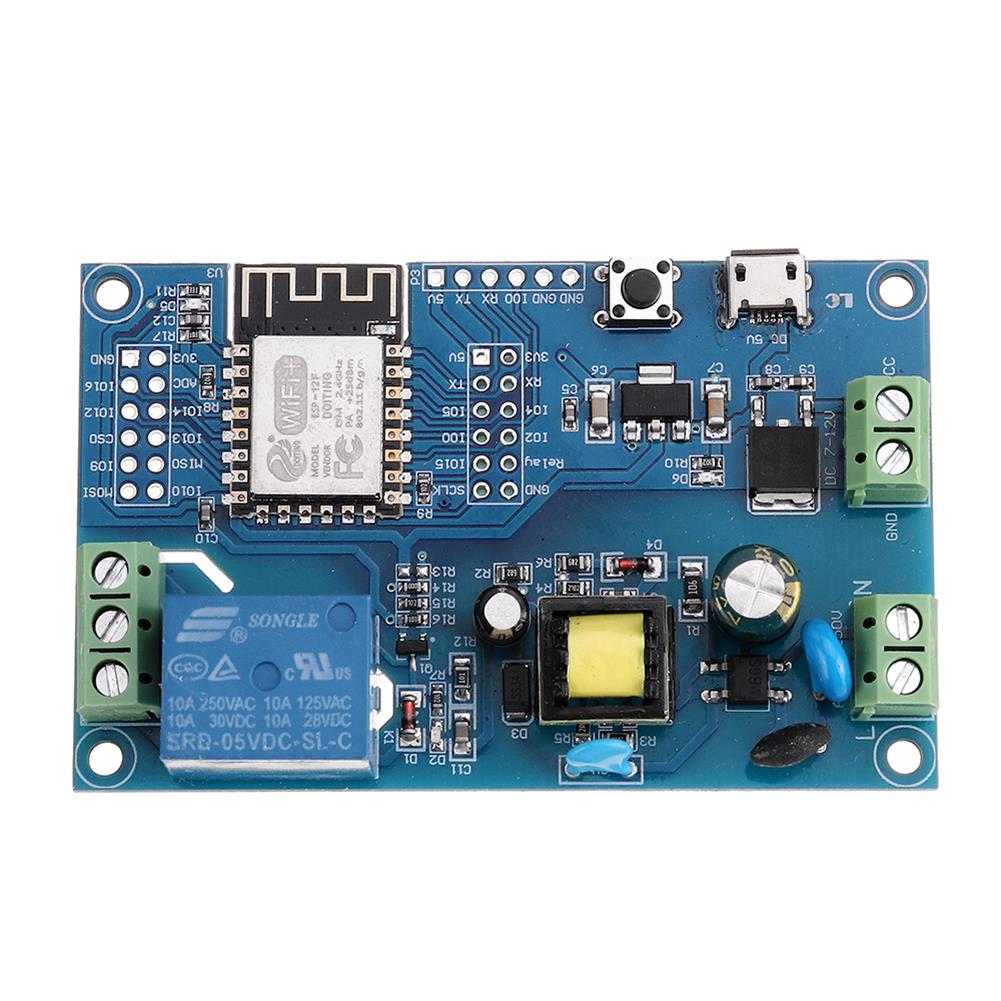
1. On-board mature and stable ESP-12F WIFI module, large capacity 4M Byte Flash
2. The I / O port and UART program download port of the WiFi module are all exported, which is convenient for secondary development.
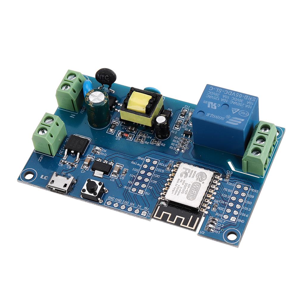
3. On-board AC-DC switching power supply module, power supply mode supports AC90-250V / DC7-12V / USB5V
4. On-board WIFI module RST reset button
5. ESP-12F supports the use of development tools such as Eclipse / Arduin IDE, and provides reference programs under the Arduin development environment.
6. One 5V relay on board, output switching signal, suitable for controlling load with working voltage within AC250V / DC30V
7. Onboard power indicator, 1 programmable LED and relay indicator
Function
1. L, N:AC90-250V power supply
2. AC90-250V to DC5V switching power supply (Do not touch here directly with your hand when using AC power supply !!!)
3. VCC, GND:DC7-12V power supply;
4. Micro USB:DC5V USB power supply;
Note:AC90-250V, DC7-12V, DC5VUSB can be selected as one of the three power supply methods.
5. 6X6mm button:ESP8266 reset button;
6. UART program download port:GND, RX, TX, 5V of ESP8266 are connected to GND, TX, RX, 5V of the external TTL serial module respectively. IO0 must be connected to GND when downloading, and then disconnected connection;
7. GPIO pin out port;
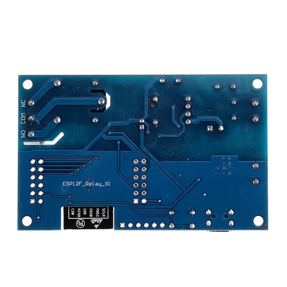
8. Relay output
Normally closed end, the relay is short-circuited to COM before pull-in, and suspended after pull-in;
COM:public end;
NO:Normally open, the relay is suspended before the pull-in, and shorted to COM after the pull-in.
9. Power indication LED;
10. Programmable LED;
11. Relay Indication LED:Lights up during pull-in.
Introduction to GPIO terminal
Number:Name:Function:Number:Name:Function
1:GND:Power ground:13:IO10:GPIO10
2:Relay:The relay drive port is driven by IO5 by default. If you want to use other I / O to drive the relay, you can remove R14, and then connect the I / 0 of the drive relay to this Relay pin:14:MISO:Slave output master input
3:IO2:GPIO2; UART1_TXD:15:IO13:GPIO13; HSPI_MOSI; UART0_CTS
4:IO4:GPIO4:16:IO14:GPI014; HSPI_CLK
5:RX:UART0_RXD; GPIO3:17:ADC:A / D conversion result. Input voltage range 0 ~ 1V, value range:0 ~ 1024
6:3V3:3.3V power supply:18:3V3:3.3V power supply
7:SCLK:clock:19:MOSI:Master output Slave input
8:IO15:GPIO15; MTD0; HSPICS; UART0_RTS:20:IO9:GPIO9
9:IO0:GPIO0:21:CS0:Chip Select
10:IO5:GPIO5:22:IO12:GPIO12; HSPI_MIS0
11:TX:UARTO_TXD; GPIO1:23:IO16:GPIO 16
12:5V:5V power supply:24:GND:Power ground
Package includes
1 x Development Board
Additional information
| Weight | 0.04 kg |
|---|


Reviews