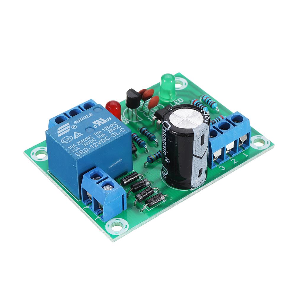
Features
1) high-accuracy voltage detection circuit;
2) terminal of the charger using high voltage device;
3) Built-in three-stage over-current detection circuit (over-current 1, over-current 2, or load short circuit);
4) MOS transistor can control the battery charge and discharge;
5) low standby current consumption.
Specifications
Overcharge voltage range:4.25-4.35v±0.05v
Size:35*35*3.6mm
Over-discharge voltage range:2.3-3.0v±0.05v
Upper limit working current:10A
Upper limit instantaneous current:20A
Quiescent current:less than 30uA
Working temperature:-40— 50 °C
Storage conditions:-40– 80 ° C
Internal resistance:less than 100mΩ
Short circuit protection:protection, charge recovery
Charging voltage 16.8V-17V
Components:S-8254AA protection chip and D403
BMS Solder Instruction
B+ connected battery positive;
B1 the connect point between battery 1 and battery 2
B2 connect the point between battery2 and battery 3
B3 Connect the point between battery 3 and battery 4
B- connect to battery negative end
P- + connection charge / discharge positive;
P- connection charge / discharge negative
Note
1. This protection board can not be used for lithium iron phosphate battery, xenon lamp, hand drill battery pack, electric fish battery pack, electric bicycle battery pack, baby car battery, 775 (4A) or above motor, 1W fisheye LED lamp, Customers who purchase in the above combination should pay attention!
The power range described applies to the following products:low power inverters, massager battery packs, LED light backup power supplies, electronics, solar street light battery packs, monitoring backup power supplies, and other products.
2. For discharge products above 3A, the discharge rate of the battery should be more than 3C.
Magnification calculation formula:1C rate battery, 2000 capacity is equal to 2AH*1=2A upper limit working current.
3C rate battery, 2000 capacity is equal to 2AH*3=6A upper limit working current.
In the use of the battery will be hot, the battery rate is not applicable, this situation can not be used for a long time, the battery will be damaged quickly.
3. Strictly connect the wiring according to the diagram 0V (B-), 3.7V (B1), 7.4V (B2), 11.1V (B3), 14.8V (B+), do not intentionally short circuit!
4. After the line is connected, you need to charge it first to have output.
5. When connecting 4 groups of batteries in series, please ensure that the voltage of each group of batteries is the same. If they are different, please fill each group of batteries separately and use them in series. In the discharge test, the battery with a fast voltage drop is a poor battery.
6. Do not mix good battery and poor battery! The closer the capacity/internal resistance of the 4 batteries is, the better! (The effect of 2 good batteries + 2 poor batteries = the effect of 4 poor batteries).
Package Included
1 x li-ion BMS PCM Battery Protection Board
Additional information
| Weight | 0.006 kg |
|---|


Reviews