Features
-Under the control of single-chip microcomputer program, which pin of single-chip microcomputer outputs low level, the corresponding LED lights up, and each LED can be programmed to light up at every moment.
-51 single chip microcomputer control LED is the foundation of learning single chip microcomputer. It is suitable for beginners and lovers of single chip microcomputer.
Note
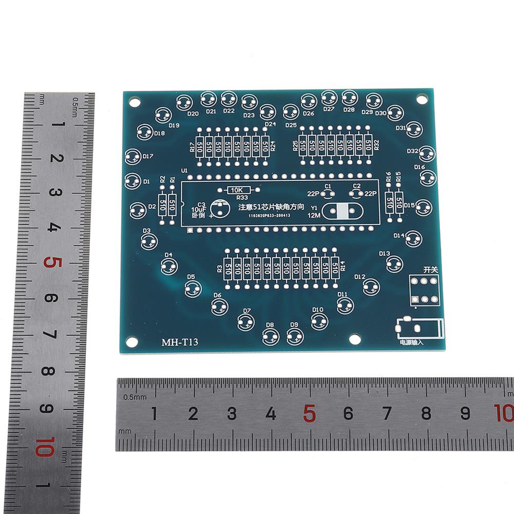
1. It is suggested to weld the resistance first, and the resistance value should be distinguished. The resistance under the MCU is 10K.
2. Then weld the crystal oscillator and 22pf capacitor, 10uF electrolytic capacitor, align the positive and negative electrodes, bend the pins, and weld them on the board, with the long pin positive electrode.
3. When welding the MCU base, the notch direction should correspond to the notch direction marked on the board, and pay attention to the direction when inserting the chip.
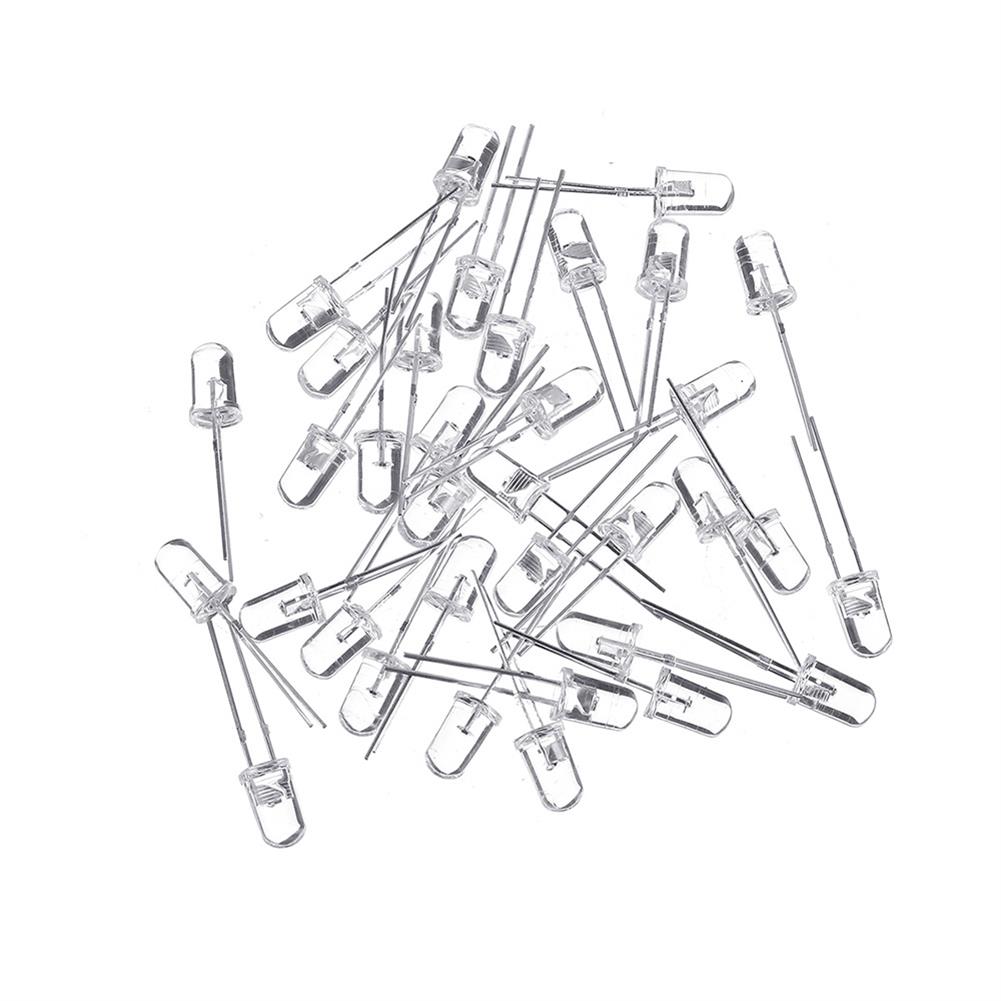
4. Pay attention to the positive and negative poles of the LED, the positive pole of the long leg, and the positive pole is on the side of the + sign on the board.
5. Finally, weld the switch and the power base, and the switch is not separated from the direction. After welding, check welding short circuit and false welding, and then power on.
6. The power supply voltage is DC 4.5-5.0v. It is not recommended to use the power bank for power supply, and the output will be automatically turned off.
Package Included
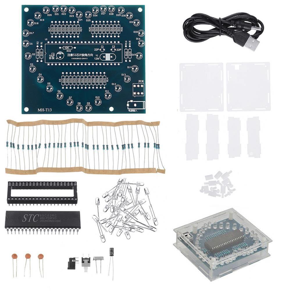
1 x Electrolytic capacitor
1 x Singlechip
1 x Chip Base
1 x Crystal oscillator
1 x Switch
1 x Female Socket
1 x Power Supply
1 x PCB
2 x Resistance(10K)
3 x Ceramic Chip Capacitor
35 x Resistance(510┯)
35 x LED
Additional information
| Weight | 0.125 kg |
|---|






Reviews