Functional description
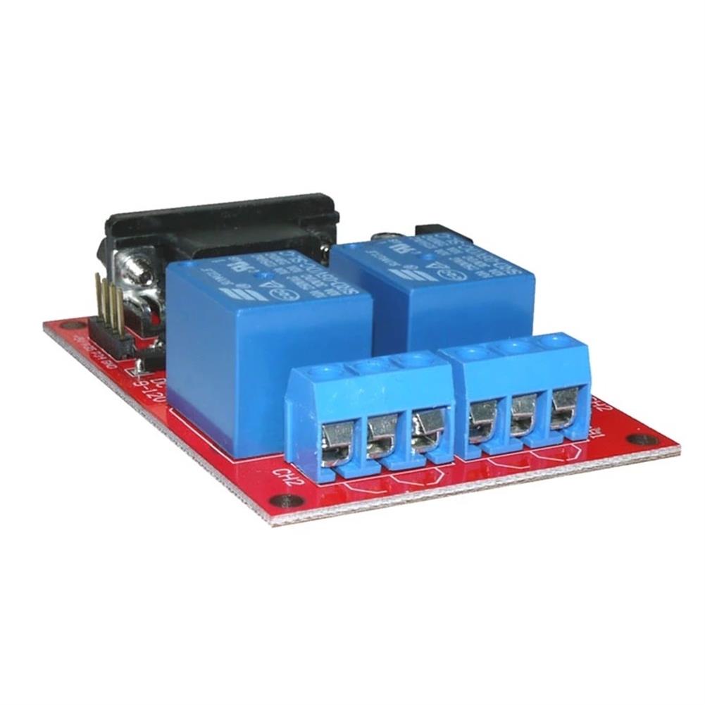
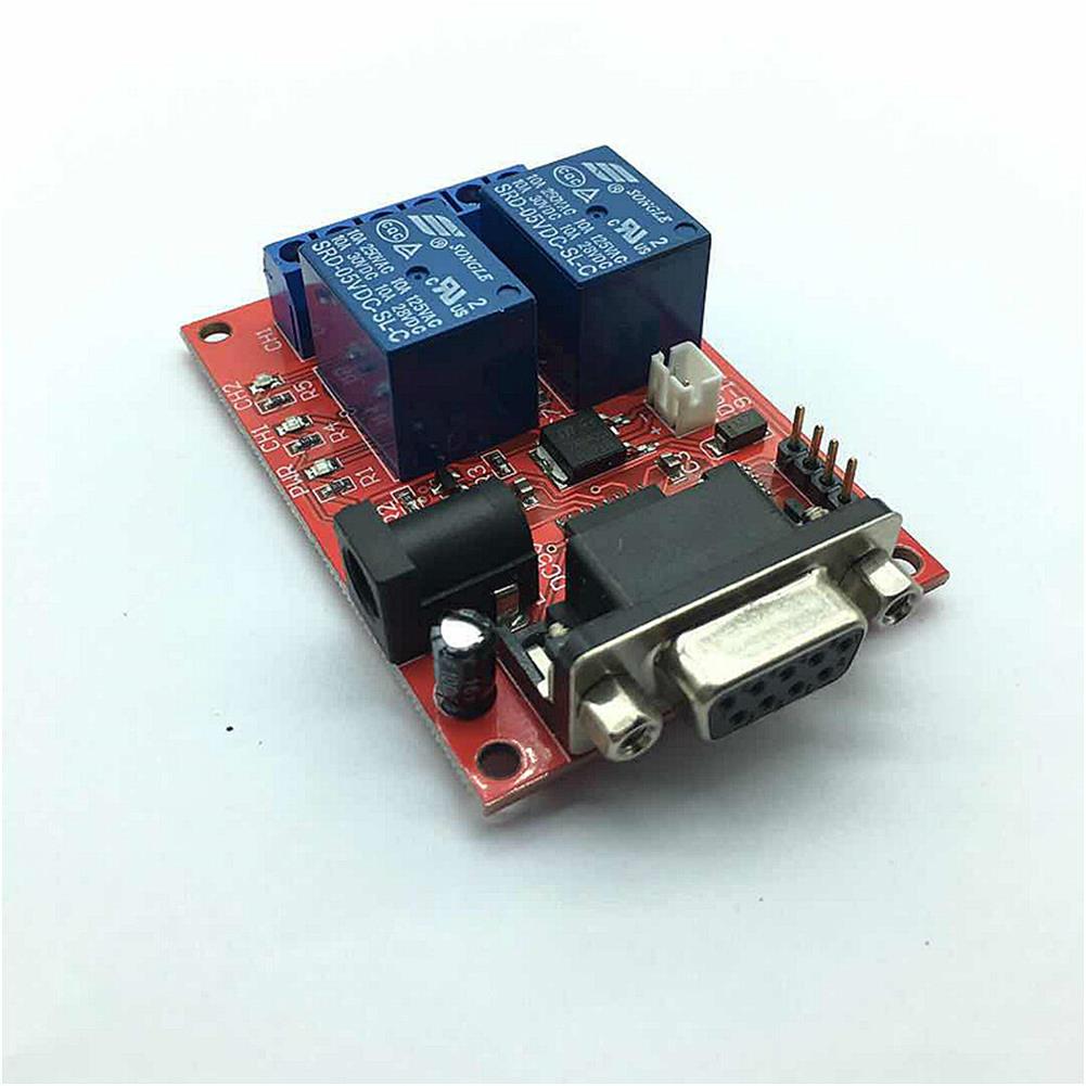
The improved SR-104 module uses patch technology to support 5V or 9-12V input voltage. Control the absorption and release of 2-way relay by serial command.Set 1-255 seconds delay independently for each channel This is the case. The operation is simple, most of the serial instructions need only 1 byte to realize the function. Provide VB upper computer program and source code, more easily realize computer remote control. After receiving each instruction, the module returns the latest status of all relays. In addition, the module can also respond to relay status queries from the host computer program. The upper computer program can judge the success of each operation by these feedback from the module, and improve the accuracy of control. SR-104A can be extended to one more MO-94C 2 Relay Module Four relays are controlled by serial port.
Module features
STC15F104W as main control chip
Set 1-255 seconds delay independently for each channel
Easy to operate, most serial instructions are single-byte instructions
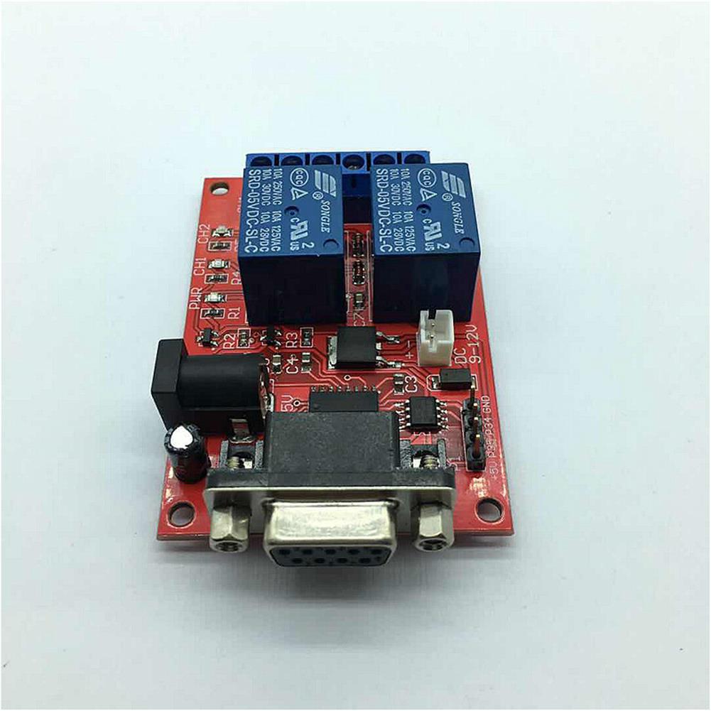
On-board 2-way relay
Relay with Absorbing Diode Circuit
Each road has LED light, light on relay suction
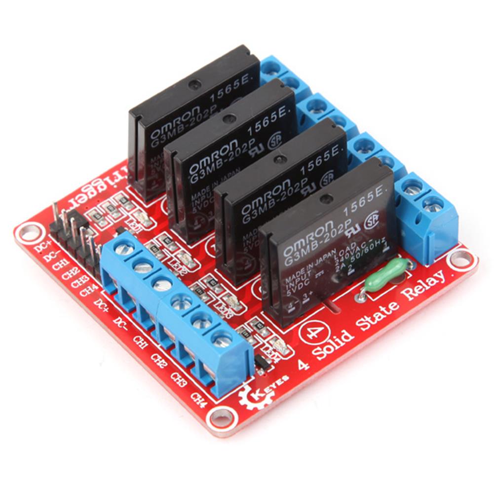
A MO-94C module can be extended to control four relays through serial port.
With 1 power supply indicator lamp
Improvement of working stability of filter circuit with capacitance
Support 5V or 9-12V input voltage
1.6 mm thick PCB is made of military grade FR-4 sheet metal with reserved mounting holes.
PCB size:71mm x 47 mm
Weight:46 g
Power requirements:DC4.5V-5V, positive and negative; or DC9-12V
Interface Description
VCC:Extended Module Power Supply Positive Pole
GND:Extended Module Power Negative
P34:CH3 Control Line, High Level Effective
P35:CH4 Control Line, High Level Effective
Blue terminal:User load, can use 220V AC equipment, or less than 30V DC equipment, the current of the equipment can not exceed the relay standard load. Each relay has a constant open contact, a constant closed contact and a common contact. When the relay is sucked in, the common contact and the constant open contact are turned on; when the relay is released, the common contact and the constant closed contact are turned on.
Package included
1 x Relay Module
Serial communication mode
Serial port communication rate 9600 bps, relay control command byte format
7 6 5 4 3 2 1 0
0 0 Command code CH4 CH3 CH2 CH1
Command code description and examples
Bit 5 Bit 4 function Example
0 0 Setting up 4-way relay status according to bit 3-bit 00x0A absorbs CH4 and CH2 and releases CH3 and CH1 simultaneously.
0 1 Make the relay selected by bit 3 to bit 0 suck in 0x1A absorbs CH4 and CH2 without changing the state of CH3 and CH1.
1 0 Release the selected relay of bit 3 to bit 00x2A releases CH4 and CH2 without changing the state of CH3 and CH1.
1 1 Return to 4-way relay status0x3A does not change the state of any relay
Delay Relay Command Byte Format and Description
7 6 5 4 3 2 1 0
1 High/Low PositionDelay time. Bit 6 = 1 represents 4 bits of high delay seconds and Bit 6 = 0 represents 4 bits of low delay seconds.
When sending delayed instructions, the higher 4 bits are sent before the lower 4 bits are sent. After sending four high bits, you must send four low bits in one second.
There is no need to send the full 8-bit delay seconds, only 4 bits lower when the delay is 1-15 seconds, and only 4 bits higher when the delay seconds are 4 bits lower than 0.Channel selection-
00:CH1
01:CH2
10:CH3
11:CH4
Delay command example
operationinstructionsExplain
CH1 Delay 3 seconds0x8CSingle byte instruction
CH2 Delay 10 seconds0xA9Single byte instruction
CH3 Delay 20 seconds0xC5, 0x91Send 2 bytes in a second
CH4 Delay 32 seconds0xC9Single byte instruction
Each time the command byte is accepted, the latest relay state will be returned. Bit 3 to bit0 is 1 for the suction state and 0 for the release state.
7 6 5 4 3 2 1 0
0 0 0 0 CH4 CH3 CH2 CH1
VB upper computer relay control operation instructions
1. When the host computer program starts, it will scan the serial port available to the computer. Please select the serial port connected with the module.
2. Click on ‘Open the serial port ‘Button
3. Select command code
4. Select the channel to operate, including two on-board relay channels and two extended relay channels.
5. Click’Send instruction’Button
6. The interface shows the instruction code sent by serial port and the value returned by module for users’reference.
VB host computer delay relay operation instructions
1. When the host computer program starts, it will scan the serial port available to the computer. Please select the serial port connected with the module.
2. Click on ‘Open the serial port’ Button
3. Select ‘1xxx:Start Delay Relay’
4. Select the channel to operate, including two on-board relay channels and two extended relay channels.
5. Set the delay time, ranging from 1 to 255 seconds
Additional information
| Weight | 0.04 kg |
|---|


Reviews