


Parameter
Input voltage:DC 5V-36V
Output voltage:DC 1.25V-32V (continuously adjustable)
Output current:4.5A adjustable, up to 5A
Output power:50W adjustable, maximum 75W
Working temperature:-40°C ~ +85°C
Working frequency:180KHz
Conversion efficiency:up to 96%
Short circuit protection:yes
Over temperature protection:yes (automatically turn off the output after over temperature)
Installation method:4 3mm silk
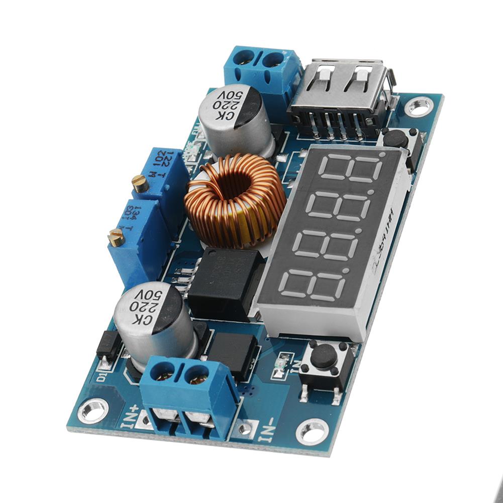
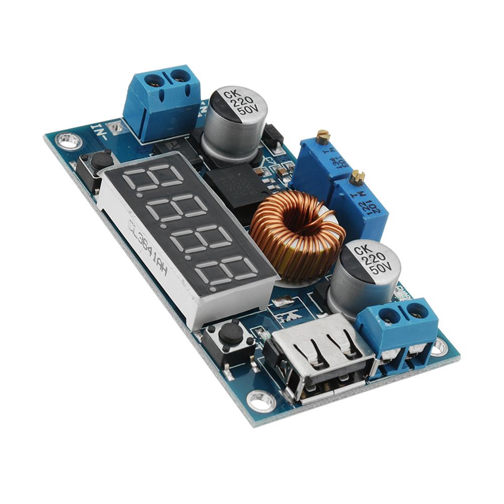
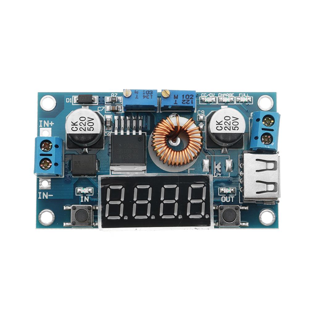
Wiring method:terminal block or soldering terminal, V-IN is input, V-OUT is output
Size:68.2*38.8*15mm (length*width*height)
Weight:35g
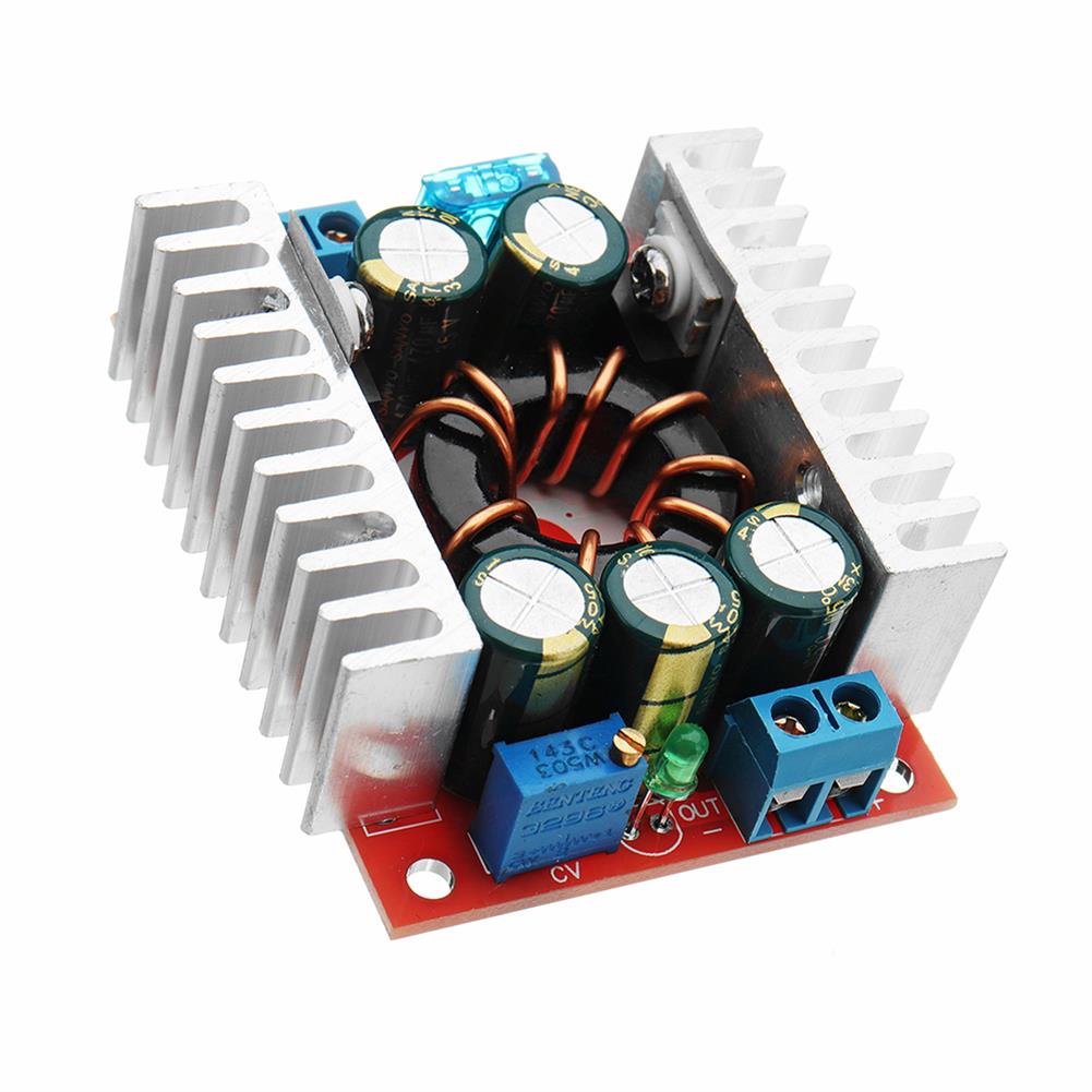
Highlight
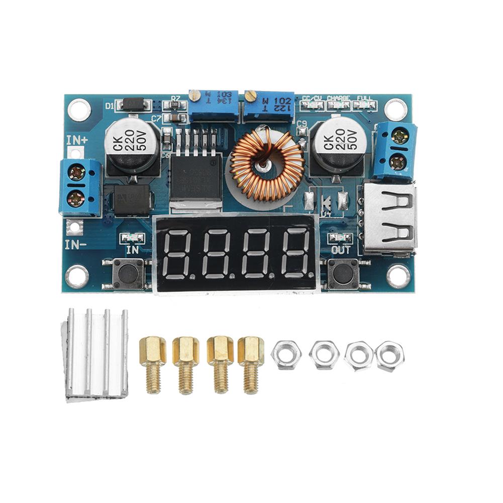
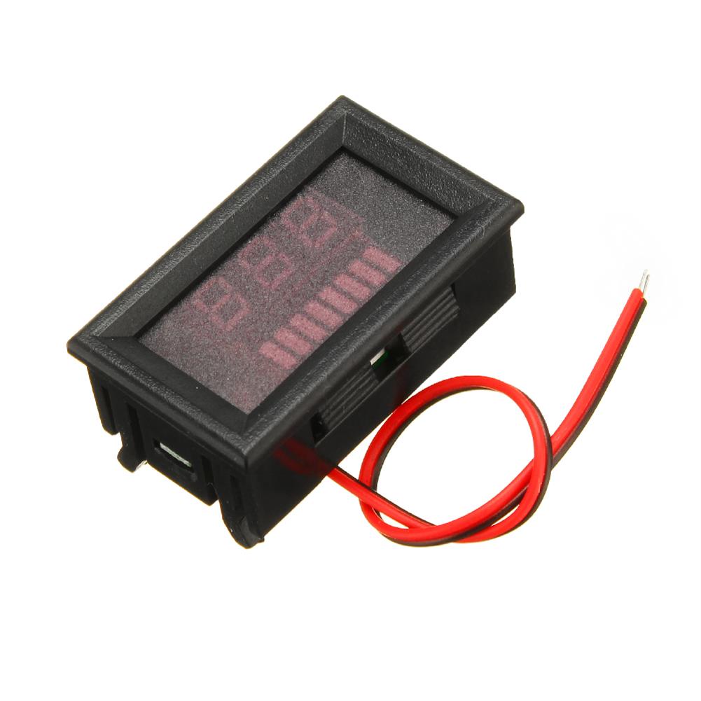
1. On-board voltage, current, and power meter, you can easily use this module without a multimeter, which is simpler and more intuitive;
2. Onboard USB interface for easy charging of your digital products; (note:the USB output voltage is consistent with the module output voltage. It is not a fixed 5V output. Please confirm to 5V before charging the USB device, otherwise it may damage your device)
3. High power, high efficiency, 5A, low ripple;
4. Three major functions
(1) used as a normal step-down module with overcurrent protection capability;
(2) it is used as a charger for various voltage value lithium batteries, batteries, nickel-cadmium nickel-hydrogen batteries (battery packs), and used in solar panels, wind turbines, etc.;
(3) used as a high power LED constant current driving module;
5. There are two modes of constant voltage and constant current, and there are indicators to indicate which mode the module is currently in;
6. When used as a lithium battery charger, you can set the float voltage and charge current, and the indicator light indicates whether it is charging or is full;
7. With current limiting protection;
8. The onboard voltage and ammeter can be self-calibrated;
9. With heat sink.
Application range
1. As a normal buck module with overcurrent protection.
Instructions
(1) Press the right button to adjust the digital meter to the [display output voltage] interface, and adjust the “constant piezo transistor Inch to make the output voltage reach the desired voltage value;
(2) Adjust the digital meter to the [display output current] interface, directly short the output end of the module (find a thick wire to short the output end), adjust the inchconstant current potentiometerinch to make the digital meter the current value reaches the preset overcurrent protection value; (for example, if the current value displayed by the onboard ammeter is 4A, then the maximum current of the module is limited to 4A, and the red indicator light is bright when the current reaches 4A)
(3) Connect the load and work.
2. Use as a battery charger.
Instructions
(1) Determine the float voltage and charge current of the battery; (if the lithium battery parameter is 3.7V / 2200mAh, then the float voltage is 4.2V, and the maximum charge current is 1C, ie 2200mA)
(2) Under no-load conditions, adjust the digital meter of the module to the [display output voltage] interface, and adjust the inchconstant piezoelectric positionerinch to make the output voltage reach the float voltage;
(3) Adjust the digital meter to the [display output current] interface, and directly short the output end of the module (find a thick wire to short the output end), then adjust the inchconstant current potentiometerinch to make the digital meter The current value reaches a preset charging current value;
(4) The charging lamp current defaults to 0.1 times the charging current; (the battery is gradually reduced during the charging process, gradually changing from constant current charging to constant voltage charging, if the charging current is set to 1A, then when When the charging current is less than 0.1A, the blue light is off, the green light is on, and the battery is charged.
(5) Connect the battery and charge it.
(Steps 1, 2, 3, and 4 are:input terminal is connected to the power supply, and the output terminal is not connected to the battery.)
3. As an LED constant current drive module.
Instructions
(1) Determine the operating current and maximum operating voltage at which you need to drive the LED;
(2) Under no-load conditions, adjust the digital meter to the [display output voltage] interface, adjust the inchconstant piezoelectric positionerinch to make the output voltage reach the LED working voltage;
(3) Adjust the digital meter to the [display output current] interface, and directly short the output end of the module (find a thick wire to short the output end), then adjust the inchconstant current potentiometerinch to make the digital meter The current value reaches a preset LED operating current;
(4) Connect the LED and test the machine.
(Steps 1, 2, and 3 are:input is connected to the power supply, and the output is not connected to the LED light)
Note
1. The input ground and output ground of the module should not be together. This will cause the module current sampling resistor to bypass, so that the module can not adjust the output current, and it is easy to burn the module when the load is connected;
2. The output of the module has a current sampling resistor. After the load is connected, there will be a voltage drop of 0V~0.2V, which is normal.
Package included
1 X DC to DC 12V turn 5V step down module
Additional information
| Weight | 0.037 kg |
|---|


Reviews