Description
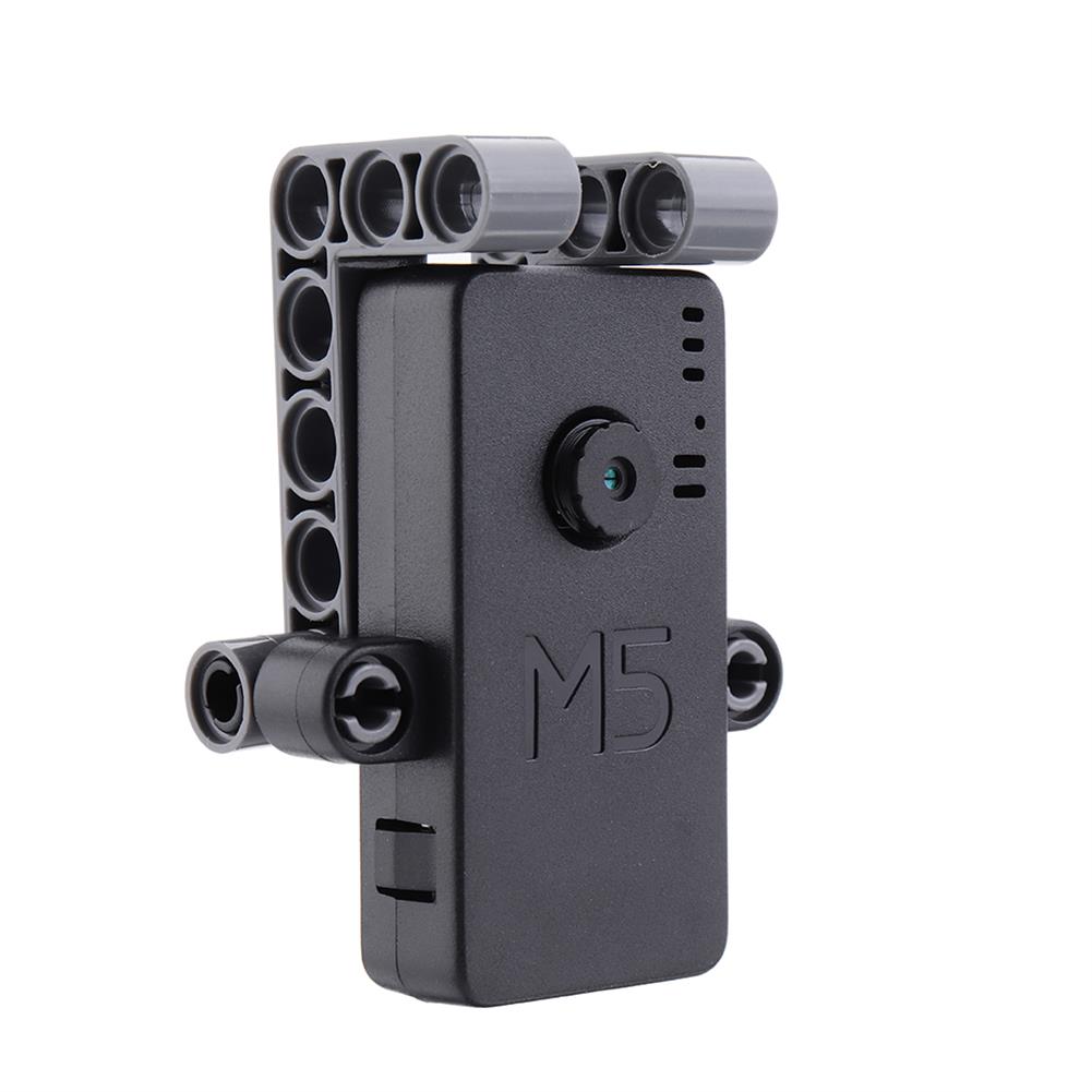
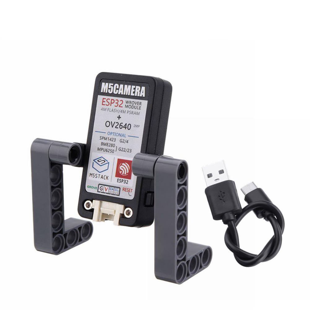
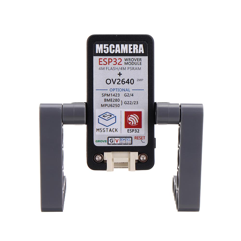
M5Camera is a development board for image recognition. It features an ESP32(4M Flash + 520K RAM) chip and 2-Megapixel carmera(OV2640).M5Camera offers plenty of storage, with an extra 4 Mbyte PSRAM. It also supports image transmission via Wi-Fi and debuging through USB Type-C port.
The hardware comes preloaded software, programmed by ESP-IDF. It is an application to run Wi-Fi camera. The output image is size 600*800, since it’s 2-Maga camera, you sure can optimize the software to output the maximum size of photos.
What this software can do
Power the board via USB type-C or GROVE
Use your phone to Wi-Fi scan an AP name start with ‘m5stack-‘ and click to connect this AP.
Open up web browser on your phone and visit 192.168.4.1
Then here comes the picture. Video is about 5-6 frames per senconds. not super fast.
The hardware also comes with some reserved weld pad, just if you want put these chips back on board.
– 9-axis gyroscope (MPU6050)
– pressure sensor (BME280)
– Analog MIC (SPQ2410)
– Lipo Battery power pins
Features
1. ESP32 module features
– Integrated dual-core Tensilica LX6
– Up to 240MHz clock frequency
– 4MB internal RAM
– 4MB Flash memory
– Integrated 802.11 BGN WiFi and dual mode Bluetooth (Classic Bluetooth and BLE)
– Hardware encryption (AES, SHA2, ECC, RSA-4096)
2. CP2104 USB to serial port
3. OV2640 camera driver
– Output format (8-bit)
YUV(422/420)/YCbCr422
RGB565/555
8-bit compressed data
8-/10-bit Raw RGB data
– Maximum transfer rate of the picture
UXGA/SXGA:15fps
SVGA:30fps
CIF:60fps
– Scan mode:Progressive
4. Camera features
– CCD size:1/4inch
– Visual range:65 degree
– Maximum pixel:2 mega
Package Included
1 x Type-C USB
1 x M5Camera Unit
1 x Instruction Manual
PinMap
Interface
Camera Pin
M5Camera(A model)
SCCB Clock
SIOC
IO23
SCCB Data
SIOD
IO25
System Clock
XCLK
IO27
Vertical Sync
VSYNC
IO22
Horizontal Reference
HREF
IO26
Pixel Clock
PCLK
IO21
Pixel Data Bit 0
D2
IO32
Pixel Data Bit 1
D3
IO35
Pixel Data Bit 2
D4
IO34
Pixel Data Bit 3
D5
IO5
Pixel Data Bit 4
D6
IO39
Pixel Data Bit 5
D7
IO18
Pixel Data Bit 6
D8
IO36
Pixel Data Bit 7
D9
IO19
Camera Reset
RESET
IO15
Camera Power Down
PWDN
see Note 1
Power Supply 3.3V
3V3
3V3
Ground
GND
GND
GROVE Interface
Grove
M5Camera(A model)
SCL
IO13
SDA
IO12
5V
5V
GND
GND
LED Interface
LED
M5Camera
LED_Pin
IO14
The following tables are Reserved Chip Interfaces
BME280 Interface
It’s IIC address is 0x76.
BME280
M5Camera
SCL
IO23
SDA
IO22
MPU6050 Interface
It’s IIC address is 0x68.
MPU6050
M5Camera
SCL
IO23
SDA
IO22
MIC(SPM1423) Interface
MIC(SPM1423)
M5Camera
SCL
IO2
SDA
IO4
NOTE
Camera Power Down pin does not need to be connected to ESP32 GPIO. Instead it may be pulled down to ground with 10 kOhm resistor.
Related Link
Offical Video
Forum
Datasheet – ESP32 – OV2640
Code
Firmware
A Model
B Model
Example
Face recognition
Serial communication-A Model
Serial communication-M5Core (The serial communication routine is the communication between the camera and the M5Cor.)
QRcode
Additional information
| Weight | 0.041 kg |
|---|







Reviews